Producing a Reliable Orthomosaic: Key Checks for Accurate Site Maps
An orthomosaic is the foundation of many mapping projects. It combines dozens or hundreds of individual aerial images into a single, geometrically corrected composite that can be measured like a map. But producing one that is truly accurate requires more than just pushing a button. Small errors in the input images or processing settings can shift features by meters, ruin the alignment of overlapping photos, or create visible seams that make the final product unusable.
This article walks through the practical checks that matter most when processing aerial imagery into an orthomosaic. Whether you are working with data from a drone or another platform, these points will help you catch problems early and deliver a site map that holds up under scrutiny.
Check the Raw Imagery Before You Start
The quality of your orthomosaic is set by the quality of the individual frames. If the source images have blur, inconsistent exposure, or missing metadata, no amount of processing can fix them. Begin by reviewing every image for motion blur or focus issues. A quick zoom to 100% on a few frames across the dataset will reveal whether the shutter speed was fast enough for the flight conditions. Even a single blurred image can degrade the alignment of its neighbors in the photogrammetry engine.
Next, confirm that the images carry accurate GPS coordinates and, if available, camera orientation data. Most drone software embeds this information in the EXIF tags automatically, but it is worth verifying with a metadata viewer. Incorrect or missing coordinates force the processing engine to rely purely on image matching, which works well for textured terrain but can fail on uniform surfaces such as grass, water, or pavement. That failure often shows up as misaligned strips or large gaps in the final orthomosaic.
Verify Overlap and Ground Sampling Distance
Photogrammetry software needs enough visual overlap between adjacent images to reconstruct the terrain in three dimensions. A common rule of thumb is 75% forward overlap and 60% side overlap for open terrain, with higher values for areas with tall structures or dense vegetation. Before you load the images into your processing pipeline, check the actual overlap values. Some software packages report this during the image import step. If the overlap falls below the recommended threshold, consider whether the site geometry allows you to proceed or if a reflight is necessary.
Ground sampling distance (GSD) is another critical parameter. It describes the real-world size of one pixel in the image. A GSD of 2 centimeters means each pixel represents a 2 cm square on the ground. The smaller the GSD, the finer the detail you can resolve, but the trade-off is larger file sizes and longer processing times. Verify that the GSD matches the project requirements. For example, a site map used for volumetric calculations can tolerate a coarser GSD than one used for infrastructure inspection. If the GSD varies across the dataset due to changes in flight altitude or camera settings, the orthomosaic will show inconsistent detail levels that can confuse downstream measurements.
Set the Correct Coordinate System and Georeferencing
An orthomosaic is only as useful as its geographic accuracy. The first thing to confirm is that all images use the same coordinate system. Mixing data in WGS84 with data in a local projected coordinate system will produce a distorted result that cannot be overlaid on other map layers. Most drone imagery is captured in WGS84 latitude-longitude coordinates, but the processing software can reproject it to a local system such as UTM or a state plane. Choose the system that matches your project's reference data, and apply it consistently from the start.
Georeferencing is the process that ties the image pixels to real-world coordinates. If your survey includes ground control points (GCPs) measured with a GPS or total station, import them before processing. GCPs correct the drift in the drone's onboard GPS and can improve absolute accuracy from several meters down to a few centimeters. When you place GCPs, spread them across the site rather than clustering them in one area. A good distribution ensures the correction applies evenly across the entire orthomosaic. For projects that do not require high absolute accuracy, such as visual site overviews, direct georeferencing from the drone's GPS may be sufficient, but always check the reported accuracy before delivering the product.
Run a Quality Check on the Point Cloud
During processing, the software generates a point cloud from the image overlaps. That point cloud is the three-dimensional skeleton from which the orthomosaic is draped. A quick visual inspection of the point cloud can reveal problems that will propagate into the final mosaic. Look for noise points that float above or below the true ground surface. These often appear over water, shiny surfaces, or moving objects such as vehicles or people. The processing software usually includes a filter to remove points below a confidence threshold, but manual review is still wise.
Also check the point density in areas that matter for your analysis. If you need an accurate digital surface model for cut-and-fill calculations, sparse point coverage over a slope will produce a smoothed surface that underestimates the true volume. In that case, adjust the processing parameters to use a stricter matching algorithm or add more images from a lower altitude. The point cloud is also where you can spot systematic errors such as a vertical offset between flight lines, which indicates that the GPS altitude data drifted during the mission.
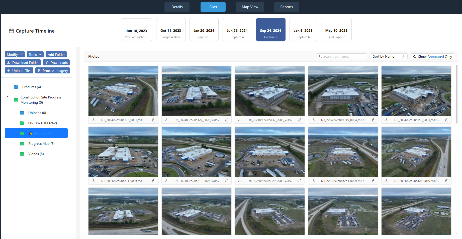
At this stage, it is worth noting that platforms like nationaldroneservices.net provide a structured environment for reviewing and comparing these intermediate outputs. Being able to load the point cloud, the orthomosaic preview, and the raw images side by side helps you catch mismatches before the final export.
Inspect the Orthomosaic for Seams and Color Consistency
Once the orthomosaic is rendered, examine it for visible seams where two images meet. A good processing engine blends the images to hide the boundaries, but differences in exposure, white balance, or sun angle can still create lines. Look at the mosaic at a zoom level that lets you see individual image boundaries, typically between 50% and 100%. If the seams are obvious, you may need to apply a color correction step or use a different blending method. Some software offers a "color balance" option that adjusts the histogram of each image to match its neighbors. Apply it and review the result.
Color consistency matters for more than aesthetics. Inconsistent color across the mosaic can confuse automated classification algorithms that rely on spectral values. For example, vegetation indices such as NDVI assume that the reflectance values are comparable across the entire site. If one part of the mosaic is brighter due to a change in cloud cover during the flight, the index values will shift, making it look as though the vegetation health changed when it did not. If your project uses multispectral imagery, pay extra attention to calibration. A reflectance panel captured before and after the flight can be used to normalize the images, but that step must be applied during processing, not after the mosaic is built.
Validate the Orthomosaic Against Reference Data
The final check is to compare the orthomosaic with known reference points. If you placed GCPs during the flight, measure their coordinates in the orthomosaic and compare them with the true coordinates. The difference is your absolute accuracy. For many mapping applications, an error of 5 to 10 centimeters is acceptable, but check your project specifications. If you do not have GCPs, compare the orthomosaic with a publicly available basemap such as satellite imagery or a previous survey. Look for consistent offsets rather than random errors. A constant shift of a few meters in one direction can be corrected by translating the entire mosaic, but random errors indicate a deeper problem with the image alignment or the camera calibration.
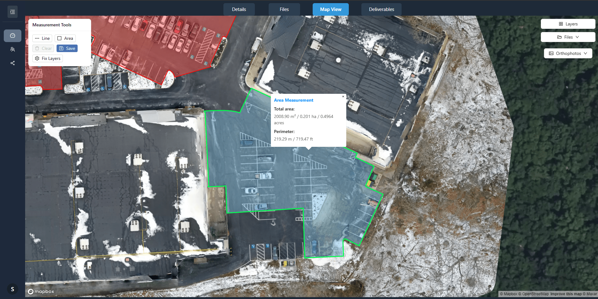
Also check the relative accuracy by measuring known distances within the mosaic. Pick two features that you know are a certain distance apart, such as the corners of a building or the edges of a road, and measure them in the orthomosaic. If the measured distance matches the true distance, the mosaic is dimensionally stable. If it does not, the ground sampling distance or the projection may be wrong. Small discrepancies can often be traced to an incorrect flight altitude or a miscalibrated camera focal length. Both parameters affect the scale of every pixel.
Document the Processing Parameters
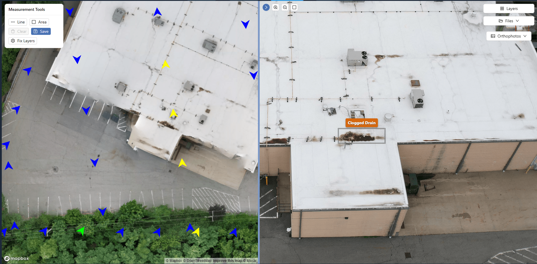
Once you are satisfied with the orthomosaic, document the settings that produced it. Note the software version, the coordinate system, the GCP coordinates if used, the overlap percentages, and any filters applied. This record is invaluable if you need to reprocess the dataset later or if a client asks how the map was made. It also helps you reproduce the results for similar sites in the future. Platforms such as nationaldroneservices.net allow you to store this metadata alongside the deliverables, making it easy to retrieve when questions arise.
Accurate site mapping depends on a methodical approach to orthomosaic processing. By checking the raw imagery, verifying overlap and GSD, setting the correct coordinate system, inspecting the point cloud, reviewing the mosaic for seams and color issues, and validating against reference data, you can produce a product that meets both visual and dimensional standards. Each check catches a different class of error, and skipping any one of them risks delivering a map that looks fine at first glance but fails under measurement.